
Initial Pile Pull-Out Test
Field Investigation | Pile Foundation Testing – HMI New Canteen Project
Project Site: HMI New Canteen Project
Client: Hyundai Motor India (HMI)
Testing Agency: Falcon Industrial Testing Laboratory Pvt. Ltd., Chennai
Location: Mevalurkuppam, Tamil Nadu
Category: Field Investigation | Pile Foundation Testing
Testing Standard: IS 2911 (Part 4):2013
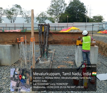
Figure 1: Overview of reaction beam, concrete pedestals, hydraulic jack, and high-strength connecting rod arrangement at HMI New Canteen project site, Mevalurkuppam.
1. Introduction
A pile pull-out test, also known as an uplift or tensile load test, evaluates a pile’s resistance to an upward force. It helps assess uplift capacity, pile displacement and the interaction between the pile surface and surrounding soil.
This blog outlines the initial pull-out test carried out at the HMI New Canteen project site in Mevalurkuppam, Tamil Nadu, with reference to IS 2911 (Part 4):2013.
2. Purpose of the Test
- Assess the pile’s uplift resistance under applied tensile loading.
- Measure vertical uplift displacement at different load stages.
- Review design assumptions related to uplift resistance.
- Study the load–displacement response and pile–soil interaction.
3. Applications
Uplift forces may arise from wind, hydrostatic pressure and other tensile actions. Pull-out testing can support the assessment of pile foundations used for transmission towers, basements, retaining structures and other structures subject to uplift.
4. Project Overview
| Project Parameter | Details |
|---|---|
| Site Location | Mevalurkuppam, Tamil Nadu |
| Test Type | Initial Pull-Out Test |
| Pile Installation | Cast-in-situ |
| Pile Diameter | 600 mm |
| Pile Length | 15.86 m |
| Design Load | 28 MT |
| Maximum Test Load | 70 MT |
| Maximum Applied Load | 70.14 MT |
5. Equipment Used
| Equipment | Purpose |
|---|---|
| Hydraulic jack and pump | Apply the upward tensile load to the test pile. |
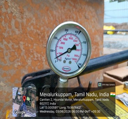
| Pressure gauge / load-measuring device | Monitor the applied load. |
| Reaction beams and bearing plates | Provide a stable reaction arrangement and transfer the load. |
| High-strength connecting rods | Transfer the pulling force to the pile connection. |
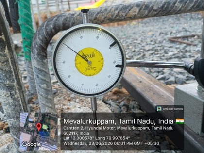
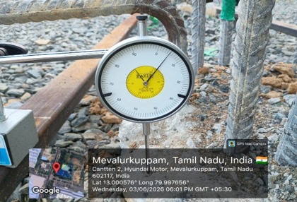
| Dial gauges (0.01 mm least count) | Measure vertical uplift displacement. |
| Datum bars and magnetic bases | Provide an independent reference for displacement readings. |
6. Test Arrangement
The reaction beams are supported on concrete pedestals or another suitable reaction system. A hydraulic jack is positioned in line with the pile connection and arranged with steel plates and high-strength connecting rods to apply the upward force. Independent datum bars and dial gauges are installed to measure pile uplift without disturbing the reference system.
7. Test Procedure
- Inspect the jack, reaction beams, connecting rods, dial gauges and reference frame before testing.
- Confirm that the reaction system is stable, sufficiently rigid and properly aligned.
- Set the dial gauges to zero and verify the calibration status of the load-measuring device.
- Apply the uplift load in controlled increments; the referenced procedure generally used increments of about 20% of the estimated safe uplift load.
- Maintain each load stage for the specified observation period or until the displacement rate becomes negligible.
- Record dial-gauge readings at the required observation intervals.
- Continue loading up to the specified test load or the applicable limiting condition.
- Unload in suitable decrements and record rebound or recovery.
- Plot the load–uplift displacement curve and review the pile response.
8. Field Investigation Gallery
Selected photographs from the pull-out test and field investigation:
9. Conclusion
The reported pile sustained a maximum applied load of 70.14 MT against a stated design load of 28 MT. The source report describes low measured uplift displacement and significant elastic recovery and concludes that the pile performance was satisfactory for the stated design load.
10. Reference
IS 2911 (Part 4):2013 – Code of Practice for Design and Construction of Pile Foundations – Load Test on Piles.
Need Pile Pull-Out (Uplift) or Foundation Load Testing?
Contact Falcon Industrial Testing Laboratory Pvt. Ltd., Chennai, to discuss field testing requirements, test pile preparation, IS 2911 standards and professional technical reporting.
Project Information
Hyundai Motor India (HMI)
HMI New Canteen Project
Mevalurkuppam, Tamil Nadu
Field Investigation | Pile Foundation Testing
Initial Pull-Out Test (Uplift / Tensile)
600 mm Dia, 15.86 m Length
Cast-in-situ
28 MT
70 MT
70.14 MT