
Initial Vertical Load Test – Perur 400 MLD Pumping Station
Pile Load Testing | CP2 Project (JWIL Site)
Date: 10-09-2026
Testing Laboratory: Falcon Industrial Testing Laboratory Private Ltd. ISO/IEC 17025:2017 NABL Accredited Laboratory
Team Members: Sharvesh R (Technical Manager, Deputy Quality Manager), V. Aravindhan (Geotechnical Engineer), S Hariharan (Geotechnical Engineer), Anima SR (Geologist), Jomey M. Susan Abraham (Geologist), Vishanth Kumar (Lab Technician)
Blog Writer: Jomey M. Susan Abraham, Geologist
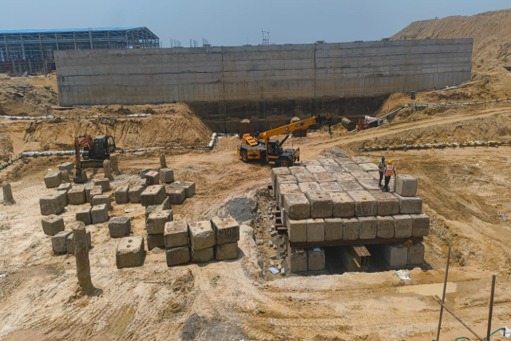
Figure 1: Overview of the 10.00 m × 10.00 m kentledge loading platform constructed at the Perur 400 MLD Pumping Station – CP2 site.
1. Introduction
Pile foundations are widely used to transfer structural loads to deeper and more competent soil strata where shallow foundations are not adequate or economical. The load-carrying capacity and settlement behaviour of piles are important considerations in foundation performance.
A Vertical Compression Load Test is carried out to evaluate the behaviour of a pile when subjected to axial compressive loading. The test provides field information on pile-soil interaction, pile displacement and the response of the pile under progressively increased loads.
This website blog presents the Initial Vertical Load Test carried out at site for the Perur 400 MLD Pumping Station – CP2 project. The test pile was identified as TP1-B and the test was conducted with reference to IS 2911 (Part 4): 2013.
2. Objective of the Test
- To determine the safe vertical load capacity of the pile.
- To measure pile displacement under compressive loading.
- To verify the design assumptions regarding vertical pile capacity.
- To study the load versus displacement behaviour of the pile.
3. Scope of the Work
- Inspection of the test pile location and preparation of the pile head.
- Preparation and installation of the reaction/loading system.
- Installation of the hydraulic jack and pressure measurement system.
- Installation of settlement measuring devices and reference arrangements.
- Application of compressive load in incremental stages.
- Recording settlement observations at specified time intervals.
- Monitoring the pile during loading and unloading stages.
- Compilation and technical documentation of field observations.
4. Test Arrangement
The pile head was chipped to remove overflowed concrete and dried bentonite slurry. The pile head was trimmed and finished to provide a smooth and level surface for uniform load transfer.
A 10.00 m × 10.00 m loading platform was constructed using structural steel sections. Three ISMB 600 sections were used as main longitudinal beams and ISMB 400 sections as cross/distribution girders. Concrete blocks were systematically stacked over the platform to provide the required kentledge.
A 40 mm thick steel plate was placed over the pile head. A 1000 MT capacity hydraulic jack was positioned centrally over the pile so that the pile, loading system and kentledge remained aligned to minimise eccentric loading.
Two datum bars were installed on either side of the pile at 2.0 m from the pile centre. Four dial gauges were mounted using magnetic bases to measure vertical displacement.
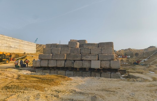
Figure 2: Systematic kentledge stacking over ISMB 600 & ISMB 400 steel girders.
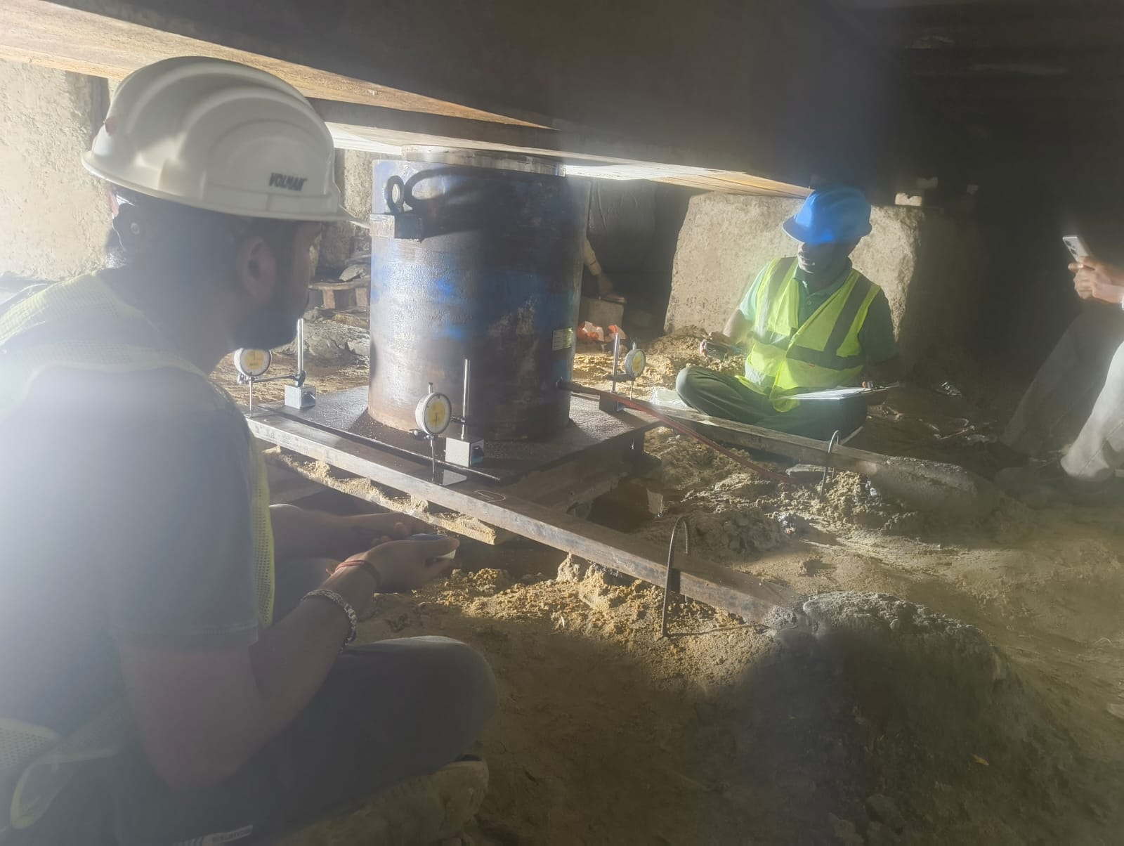
Figure 3: Technical team actively logging readings and monitoring setup under platform.
5. Test Procedure
5.1 Initial Preparation
Before loading, the hydraulic jack, reaction system, pressure gauge/load cell, dial gauges and reference beams were checked for alignment, stability and rigidity. The dial gauges were set to zero and measuring instruments were checked for calibration.
5.2 Loading Procedure
The compressive load was applied to the test pile in equal incremental stages. For the initial vertical load test described in the report, the load increment was generally not more than 20% of the safe load. Settlement observations were recorded at specified time intervals after each load increment. Further loading was applied only after completion of the required observations for the preceding stage.
5.3 Unloading / Rebound
After completion of the loading stage and required observations, the pile was unloaded in suitable decrements. Settlement recovery observations were taken during unloading, followed by final observations after complete unloading.
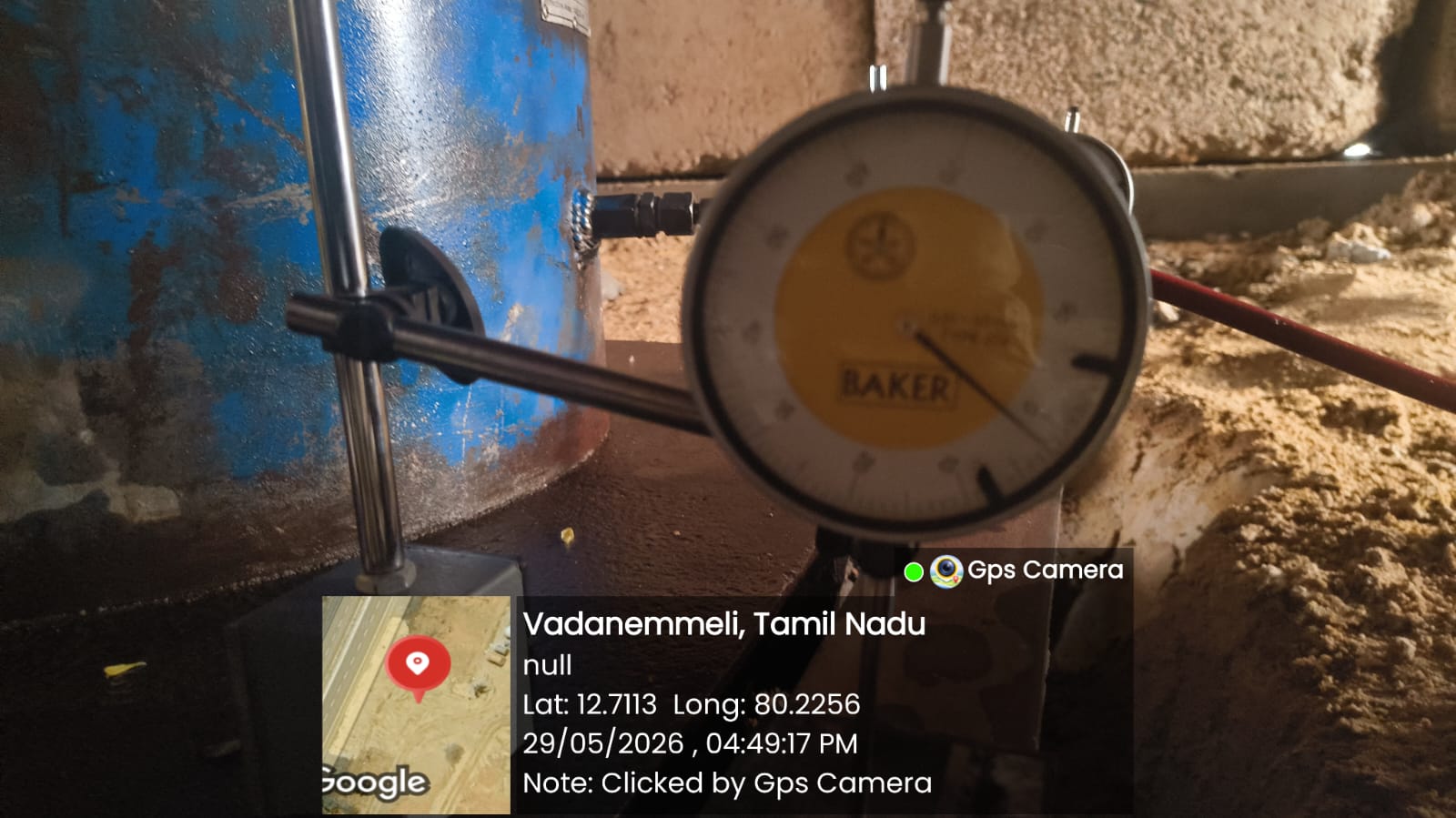
Figure 4: 1000 MT hydraulic jack aligned on pile head.
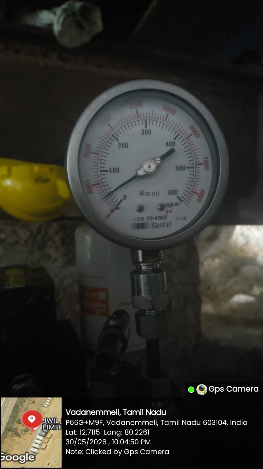
Figure 5: Baumer pressure gauge (0–600 kg/cm²).
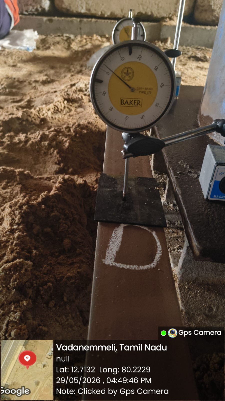
Figure 6: Dial gauge 'D' mounted on magnetic base.
6. Test Details – JWIL Site
| Parameter | Details |
|---|---|
| Project | Perur 400 MLD Pumping Station – CP2 |
| Client | Chennai Metropolitan Supply and Sewerage Board |
| Location | Perur |
| Type of Test | Initial Vertical Load Test |
| Pile ID | TP1-B |
| Pile Installation | Cast-in-Situ |
| Pile Diameter | 600 mm |
| Pile Length | 13.0 m |
| Design Load | 193.8 MT |
| Maximum Test Load | 484.5 MT |
| Reference Standard | IS 2911 (Part 4): 2013 |
7. Equipment Used
| Equipment | Specification / Identification | Purpose |
|---|---|---|
| Hydraulic Jack | 1000 MT capacity; effective area 1452.20 cm² | Application of compressive load |
| Pressure Gauge | Baumer; 0–600 kg/cm² range | Monitoring hydraulic pressure |
| Dial Gauges | 4 Nos.; 0–50 mm; least count 0.01 mm | Measurement of pile displacement |
| Datum Bars | 2 Nos.; 2.0 m from pile centre | Reference for displacement measurement |
| Magnetic Bases | For dial gauge mounting | Secure positioning of gauges |
| Steel Plate | 40 mm thick | Uniform load transfer at pile head |
| Loading Platform / Kentledge | Structural steel beams (ISMB 600 & ISMB 400) and concrete blocks | Reaction/loading arrangement |
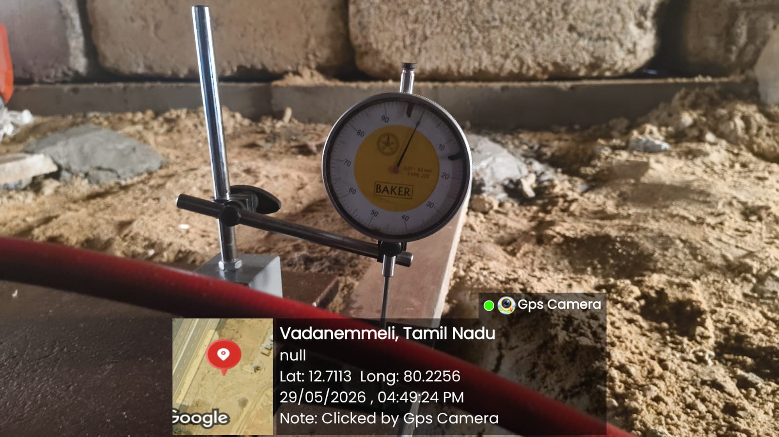
Figure 7: Dial gauge setup along reference datum bar.
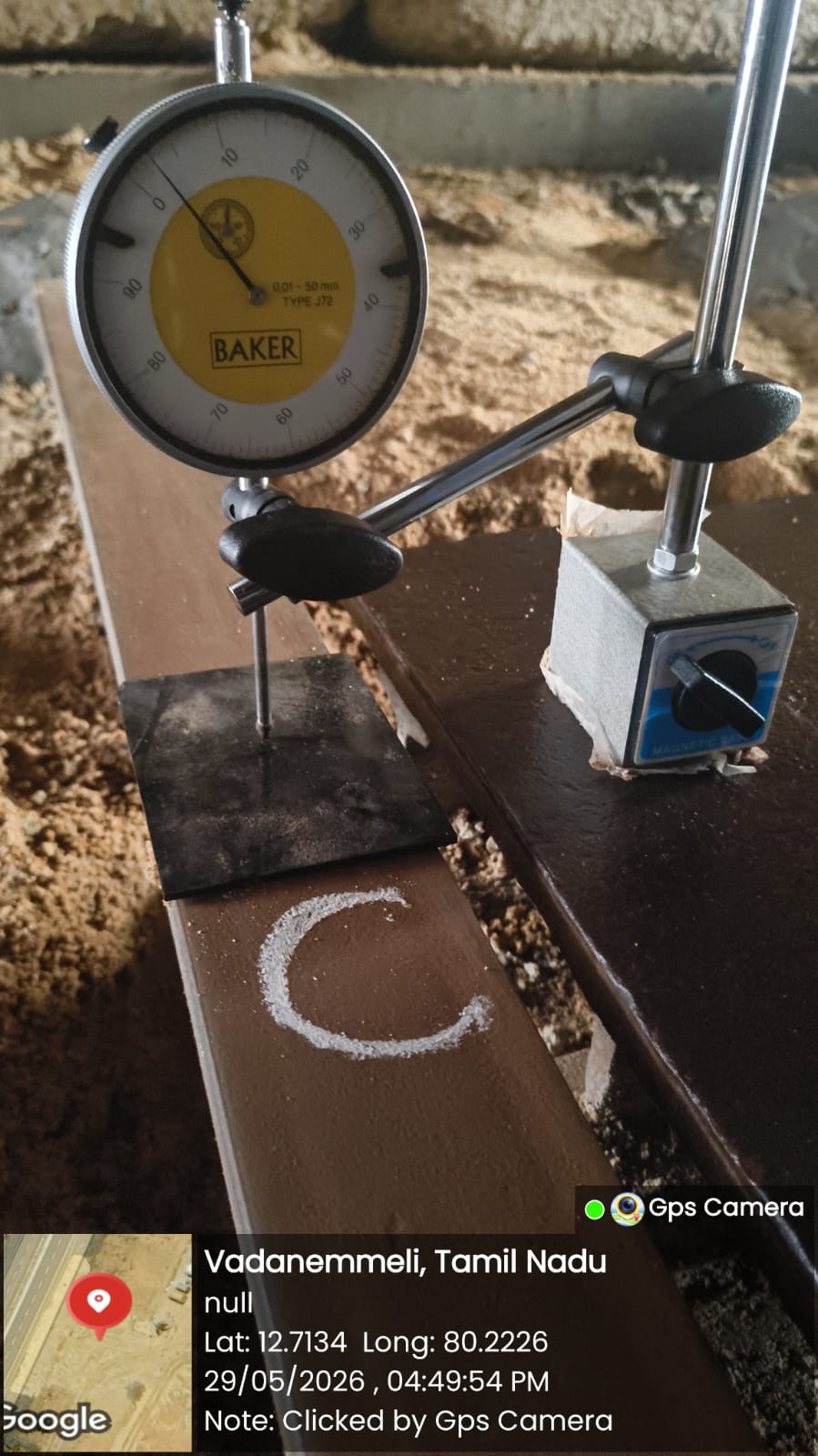
Figure 8: Dial gauge 'C' calibrated and mounted on datum bar.
8. Safety and Quality Considerations
- Ensure the loading platform and kentledge arrangement are stable before testing.
- Maintain proper alignment of the hydraulic jack and loading system.
- Keep personnel clear of the reaction/loading arrangement during loading.
- Verify the condition and calibration status of measuring instruments before testing.
- Protect dial gauges and datum/reference arrangements from disturbance.
- Record observations systematically at each specified load stage.
9. Summary
The Initial Vertical Load Test provides a controlled field method for studying the response of a pile under axial compressive loading. At the site, the test arrangement included a centrally aligned hydraulic jack, reaction/loading platform, kentledge and four dial gauges for displacement monitoring. Loading and unloading observations were recorded systematically as part of the field-testing process.
10. Conclusion
Vertical pile load testing is an important field investigation for assessing pile behavior under compressive loading. The Initial Vertical Load Test at the JWIL site was arranged to assess pile response, settlement behaviour and the relationship between applied load and displacement in accordance with the applicable testing requirements.
This website blog format intentionally excludes the project test results, load–displacement results and capacity assessment.
12. Reference
IS 2911 (Part 4): 2013 – Code of Practice for Design and Construction of Pile Foundations – Load Test on Piles.
Project Information
Chennai Metropolitan Supply and Sewerage Board
Perur (JWIL Site), Tamil Nadu
Pile Load Testing
TP1-B (600 mm Cast-in-Situ)
484.5 MT (Design: 193.8 MT)